
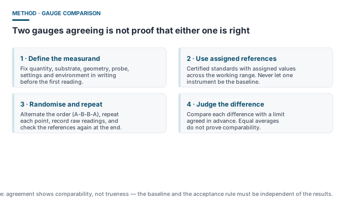
Quick answer: A comparison is not “put two gauges on one sample and see if the numbers match”. Two instruments can agree because both are wrong in the same way. A defensible comparison fixes the measurand and the conditions first, uses reference standards with assigned values at several points across the range you actually work in, randomises the reading order, repeats each point, and checks the differences against an acceptance rule agreed before the first reading. The reference value has to be independent of both instruments — never use one of them as the “true” answer.
When a comparison is actually needed
- A new or repaired instrument joins a team whose historical data you intend to keep using;
- Two gauges, two probes or two crews feed results into the same report or the same trend;
- A supplier’s readings and your incoming inspection disagree;
- You change method — for example from a coating gauge to an ultrasonic mode, or from one optical geometry to another;
- A reference standard batch, probe or coupling procedure is replaced, and you need to know whether the data stayed continuous.
In each case the question is not “which one is right?” but “can I treat results from both as one data set?” That is a question about comparability, not about accuracy, and resolution, accuracy and repeatability are three different things.
Step one: write down what is being compared
Most failed comparisons are really failed definitions. Agree these items in writing before any reading is taken:
| Condition | What to fix | Why it matters |
|---|---|---|
| Measurand | Which quantity: film on metal, remaining wall, transmittance at a stated band, haze or gloss at a stated geometry | Film thickness and wall thickness are not the same quantity; neither is haze the same as transmittance. |
| Sample and geometry | Substrate material and thickness, curvature, surface finish, coating or film build-up, measurement locations | A change in substrate or curvature can move a reading more than the difference between two instruments. |
| Instrument state | Probe identity, zero/adjustment state, sound velocity setting, measurement angle, warm-up and temperature equilibrium | Comparing an adjusted gauge with an unadjusted one compares their setup, not their performance. |
| Environment and operator | Cleanliness, temperature, couplant or contact pressure, handling time, who measures | Fingerprints, warm hands and drying time are real sources of scatter in optical and thickness work. |
Step two: choose the references, not a winner
Use certified reference plates, coated standards or shims with an assigned value and a stated uncertainty or tolerance, and check that their range covers the low, middle and high end of what you actually measure. An unassigned piece of foil picked from a drawer is not a reference standard; shim verification practice explains what those pieces can and cannot establish. Traceability and calibration certificates explain why a certificate alone does not make every later field reading valid.
The comparison baseline should come from the assigned values, or from an independent reference, not from the average of the two instruments. This is the same principle that laboratory intercomparison methods use: an assigned value and an assessment criterion that are independent of the participants’ results are more informative than a consensus built from those results. If both instruments drifted together, a consensus would hide it.
Step three: run the sequence
- Let instruments, probes and samples reach a stable temperature in the measuring environment.
- Check each instrument on its own reference before the comparison, following the maker’s instructions. Calibration, verification and adjustment are three separate operations — do not improvise an adjustment halfway through the run.
- Measure several reference points spanning the working range, at least a low, a middle and a high one.
- Randomise or alternate the order (A-B-B-A rather than all of A then all of B), so warm-up drift and operator fatigue do not land entirely on one instrument.
- Take repeated readings at each point and record every one of them, not just the average.
- Repeat the reference check at the end. If the closing check fails, the whole run is suspect, including the readings that looked good.
ASTM D7091-22 describes calibration, verification and adjustment as the three operational steps for coating thickness gauges, recommends verification before, during and after use, and explicitly notes that a single-point reading may not represent a coating system. Spot and area sampling logic covers the sampling side of the same problem.
Step four: judge the difference, not the agreement
For each point, look at the difference between the two series. Compare that difference with an acceptance limit agreed in advance — from the project specification, the combined uncertainty of the two measurements, or a documented internal rule. Reading measurement uncertainty explains how to interpret the “±” behind such a limit. Three cautions:
- Two averages being equal does not prove the instruments agree at the range ends, or that their scatter is similar;
- Passing at one point does not establish the whole working range;
- Do not widen the limit after seeing the numbers. If the rule has to change, record why and rerun.
If it fails, look at the setup before the instrument
- Was the same measurand measured on the same substrate, at the same point, in the same orientation?
- Was the surface clean, dry, undamaged, and free of residual film or couplant variation?
- Is the probe worn, contaminated or seated at an angle? Coupling and probe technique covers the ultrasonic case.
- Did the zero, adjustment or sound-velocity setting change during the run?
- Are the references appropriate for this substrate and this instrument type?
Then isolate the data collected since the last satisfactory verification, and review it before those results are used for acceptance. An auditable inspection record makes that boundary visible later. A short list of recurring field errors is in the measurement mistakes checklist.
What the comparison report must contain
- Instrument and probe identities, serial numbers and the reference to each calibration record;
- Reference standard identification, assigned value and stated uncertainty or tolerance;
- All raw readings, units, sequence and environmental conditions;
- The acceptance rule as written before the run, the differences found, and the conclusion;
- The action taken on any failed check, and who reviewed it.
Five common misconceptions
- “They read the same, so both are accurate” — agreement shows comparability, not trueness;
- “One point is enough” — a single point cannot reveal range-dependent bias;
- “One of the two is the reference” — that makes the exercise circular;
- “A comparison is a calibration” — it checks consistency between two measurement chains, and does not replace either instrument’s documented calibration;
- “Any film or shim will do” — an unassigned, damaged or unsuitable reference invalidates the baseline.
Done this way, a comparison produces something far more useful than a pair of matching numbers: a documented statement about whether two data sets may be merged, retained or trended together. That is the only question worth answering when the readings will end up in a customer report.
Sources
- ASTM D7091-22 — official ASTM page (calibration, verification, adjustment; reporting recommendations)
- ISO 13528:2022 — official ISO catalogue entry (statistical methods for interlaboratory comparison)
Related instruments: DONGRU DR-A5 Automotive Paint Thickness Gauge · DONGRU DR-W300 Haze Meter · Request a quote