
The bottom line
Eddy current testing measures how far the coil sits from a conductive substrate. It works only on substrates that are non-magnetic and conductive (aluminium, copper, brass, austenitic stainless steel), and only through non-conductive coatings. Both conditions must hold.
The physics: from eddy current to reading
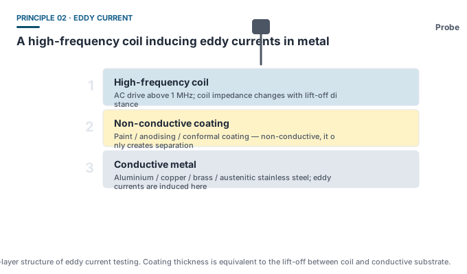
- The probe coil is driven with a high-frequency alternating current (above 1 MHz), creating an alternating magnetic field;
- That field induces closed eddy currents in the surface layer of the conductive substrate, and the eddy currents generate an opposing field;
- The opposing field changes the coil impedance. The farther the coil is from the substrate — the thicker the coating — the weaker the eddy currents and the smaller the impedance change;
- The gauge converts the impedance change into a thickness reading.
The industry term “lift-off” originally described exactly this coil-to-substrate distance. In eddy current coating measurement, coating thickness is translated into a lift-off value.
How ISO 2360 and ISO 2178 divide the work
| Magnetic induction · ISO 2178 | Eddy current · ISO 2360 | |
|---|---|---|
| Substrate requirement | Ferromagnetic (steel, iron) | Non-magnetic and conductive (aluminium, copper, brass, austenitic stainless steel) |
| Coating requirement | Non-magnetic | Non-conductive |
| Typical frequency | Low frequency | High frequency, above 1 MHz |
| Corresponding GB standard | GB/T 4956 | GB/T 4957 |
| Typical range | 0-1500 / 2000 μm, up to 15 mm | Mostly 0-1250 μm; thin-layer models to 500 μm |
Conductivity sensitivity is the biggest engineering trap
Eddy current strength depends on substrate conductivity, and conductivity is a far more restless parameter than permeability:
- Aluminium 6061 and 7075 have different conductivities, so their reading baselines differ;
- Changing the composition ratio of a copper alloy visibly shifts conductivity;
- Solution treating, ageing and annealing change conductivity;
- When the substrate itself is thin — thinner than the effective eddy current penetration depth — the reading runs low.
The engineering answer: zero the gauge on bare substrate of the same alloy and same temper, then check the slope with a shim. Never carry an aluminium calibration over to a copper part.
Applications where nothing else will do
- Anodised layer thickness on extruded aluminium — a routine quality control item for architectural and industrial profiles;
- PCB conformal coating — protective coating thickness on boards, where the substrate is copper foil and glass-reinforced composite. This is the target application for Dongru DR370A;
- Anodised layers and ultra-thin paint on aluminium and copper — DR370B covers 0-500 μm specifically for thin layers;
- Automotive aluminium wheel coatings, cookware aluminium panels and battery cell shells.
The Dongru models that use it
The pure eddy current models are DR370A (0-1250 μm, PCB conformal coating and board paint) and DR370B (0-500 μm, oxide layers and ultra-thin paint on aluminium and copper). Where both ferrous and non-ferrous parts are in play, choose a Fe/NFe dual-mode gauge — DR280A, DR380A, DR-A5, DR130. They integrate both coil sets in one probe and switch principle automatically according to the substrate.
Common misconceptions
- “Eddy current works on plastic” — no. Plastic is not conductive, so no eddy current can form. Coatings on non-metallic substrates require ultrasonic testing (ASTM D6132).
- “Calibrated on one piece of aluminium, it will be just as accurate on copper” — the conductivity difference shifts the reading systematically.
- “Eddy current is less accurate than magnetic induction” — on a compliant substrate with correct calibration the two are comparable in uncertainty. The differences come from substrate variables, not from the principle.