
The bottom line
Magnetic induction measures the distance from the probe to the ferrous substrate — not the mass or the volume of the coating. As long as the coating itself is non-magnetic and the substrate is steel or iron, the method is accurate enough across 0-2000 μm to support SSPC-PA 2 project acceptance.
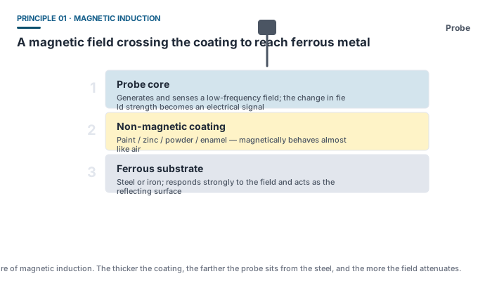
The physics: three steps per reading
A measurement takes microseconds, but it breaks down into three distinct stages:
- A low-frequency current drives the core inside the probe, creating a steady magnetic field at the probe face;
- The field crosses the non-magnetic coating and reaches the ferrous substrate. The thicker the coating, the larger the air gap in the magnetic circuit and the more the flux density drops;
- The substrate response is picked up by the probe, and the gauge compares that change against its calibrated curve to output a thickness reading.
Where it works, and where it does not
| Aspect | Works | Does not work |
|---|---|---|
| Substrate | Steel, iron (ferromagnetic metals) | Aluminium, copper, brass, stainless steel (non-magnetic); plastic, wood, concrete (non-metallic) |
| Coating | Paint, varnish, zinc plating, chrome plating, powder coating, enamel, plastic coatings (non-magnetic) | Nickel plating and other magnetic coatings (needs a different principle, see ISO 2361) |
| Surface condition | Flat or gently curved; cured dry film | Uncured wet film — the probe leaves an impression, and D7091 explicitly excludes it |
Why a new part means a new adjustment
Permeability sits in the denominator of every magnetic induction reading. Steel grades differ in permeability (carbon steel, low-alloy steel, cast iron), and cold working changes the permeability of a single piece locally. Those differences go straight into the number on the display.
ASTM D7091-22 handles this with Adjustment: take a base metal reading (BMR) on bare substrate of the same alloy and surface condition, zero the gauge there, then apply a one- or two-point shim correction. Skip this step and the reading can shift systematically by 1-3 μm or more.
How to read the measuring range
Range is set by probe geometry and drive current — not by “bigger is better”:
- 0-1250 / 2000 μm — the workhorse range for general coating work (industrial anti-corrosion, automotive paint, metal fabrication) and the one with the highest resolution, e.g. DR260A, DR280A;
- 0-3000 / 5000 μm — high-build coatings and pipeline anti-corrosion layers, e.g. DR3000, DR5000S;
- 0-6000 / 10000 μm — heavy anti-corrosion and fireproofing systems, e.g. DR6000A, DR9000A;
- 0-15 mm — intumescent fireproofing and other very thick coatings, e.g. DR15A.
The Dongru models that use it
Dongru splits its Fe (magnetic) models by range and power supply. Entry and general-purpose: DR120, DR220, DR320 (battery, 0-1500 / 2000 μm). Contractor grade: DR260A, DR360A (built-in Li-ion, 0-1250 / 2000 μm, with zinc coating weight conversion). High range: DR5000S, DR6000A, DR9000A, DR15A. All of them are Type 2 electronic instruments as defined by ASTM D7091.
Common misconceptions
- “A magnet that pulls harder means a thinner coating” — that is Type 1 magnetic pull-off logic: lower accuracy, dependent on the operator’s technique. Type 2 electronic gauges measure field strength, not feel.
- “A thicker coating must read more accurately” — the opposite. Past the top of the range the reading enters a non-linear region, and you need a different probe or a wider-range gauge.
- “Just slip a sheet of paper on the steel and subtract its thickness” — shim correction is formally defined. Arbitrary shims introduce errors you cannot trace.