
The bottom line
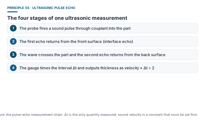
An ultrasonic thickness gauge measures exactly one thing: how long sound takes to make a round trip inside the part. Thickness is then calculated from a known velocity — so if the velocity is wrong, the reading is wrong. That is the source of the great majority of ultrasonic thickness errors.
The formula and its three consequences
The reading is thickness = velocity c × round-trip time Δt ÷ 2. The division by two accounts for the out-and-back path. That simple formula carries three engineering consequences:
- Velocity must be a known quantity. Steel is roughly 5900 m/s, aluminium about 6320 m/s, copper about 4700 m/s, glass about 5600 m/s and acrylic about 2730 m/s. Different materials, different velocities.
- An error in velocity transfers one-to-one to the reading. Velocity off by 2% means thickness off by 2% — 2 mm on a 100 mm part.
- The gauge needs a velocity calibration function. The standard practice is to back-calculate velocity from a reference block of the same material and known thickness, then measure the part.
The division of labour with a coating gauge
| Ultrasonic thickness gauge | Coating thickness gauge (magnetic / eddy current) | |
|---|---|---|
| What it measures | The thickness of the material itself | The thickness of the coating on top |
| Typical reading | Pipe wall 8.2 mm | Paint film 320 μm |
| Contact with substrate | Required, through couplant | Not required — only touches the coating surface |
| Unit convention | mm | μm or mil |
| Shared property | Non-destructive; the part is not damaged |
Why couplant is necessary
Sound travels well in solids but attenuates extremely fast in air. Even a few tens of microns of air between probe and part reflects almost all of the energy. Couplant exists to displace that air layer and conduct sound into the part.
- Routine metal parts: water-based or oil-based couplant, glycerine, machine oil;
- Rough surfaces, vertical faces, overhead work: high-viscosity couplant;
- Hot parts: high-temperature couplant;
- Surfaces that must not be contaminated (intact coatings): dry coupling or a low-frequency probe.
When you get no reading at all
- The part is too thin — below the probe near field the front and back echoes overlap and cannot be separated. Ultra-thin mode or a single-crystal probe is needed;
- Internal corrosion or heavy scale — echoes scatter, and the reading jumps or shows multiple echo interference;
- Composite parts with large velocity differences — cast iron and composites have non-uniform velocity;
- Curvature radius too small — the probe cannot make sufficient contact, and a small-diameter probe is required.
The Dongru models that use it
Dongru’s wall thickness line has five sellable models with increasing capability. DR83A (0.9-300 mm, 2.8-inch colour screen) and DR85A (0.85-400 mm) are the general-purpose pair; DR86A (0.55-500 mm, ±(0.5%H+0.05) mm) is the high-precision wide-range model; DR87A (0.55-500 mm with through-coating 3-30 mm) is the through-coating type; DR89S (0.15-300 mm, single or dual crystal) is the ultra-thin specialist.
Common misconceptions
- “An ultrasonic gauge also measures coatings” — in normal mode it measures total part thickness, coating included. Excluding the coating requires through-coating (Echo-Echo) mode; see the dedicated article.
- “No need to set velocity, the gauge works it out” — some models offer presets for common materials, but cast iron, alloys and composites must be calibrated with a measured velocity.
- “Any couplant will do, petroleum jelly is fine” — petroleum jelly works on steel, but it contaminates some surfaces and behaves very differently at temperature extremes. Choose by working condition.